Introduction |
This is an 'A' Level Design & Technology project. At the time when this was done this project was worth 15% of the marks. It helped me get an A grade in 1998. The whole project is reproduced here for your reference. The only parts of the project not shown are the photographs and the graph.
|
This is a real A-Level project and as such is intended for educational or research purposes only. Extracts of this project must not be included in any projects that you submit for marking. Doing this could lead to being disqualified from all the subjects that you are taking. You have been warned. |
Aims |
This is an experiment to see if cast iron shears at an angle of 45° and also to check if the cast iron samples breaks at pressure at which books say it should break.
Planning Strategy |
I plan to alter the compressive apparatus first to measure the force at which the cast iron samples sheared. I will then work out what size of cast iron sample the apparatus can take before making the individual samples. If I make the samples first then I could end up with 10 samples which were unsuitable for the apparatus.
The book 'S.G. Iron Properties And Applications' puts the average pressure at which cast iron shears at 98kg/mm². The maximum load that the compressive rig will produce is 350kg/mm². The maximum area of the cast iron samples can therefore be worked out.
Maximum area of cast iron samples = Maximum Compressive load ÷ Average Pressure at which iron breaks.
350kg ÷ 98kg/mm² = 3.57mm²
The maximum diameter of the samples is then worked out.

The maximum diameter that each cast iron piece can be is 2.13mm. I shall therefore make all the samples with a diameter of 2mm.
Once I have made and tested the apparatus I will make the samples. I will make them all out of the same long piece of cast iron so that the samples would be uniform. I will make them one after another so that they can be as similar as possible. If I make a few first and some more a few weeks later then small changes in the lathe settings could cause irregularities in the samples which would lead to an unfair test.
In order to make sure that the samples are all tested in the same environmental conditions I plan to do all the compressive tests in the same one hour period if possible.
Cast Iron |
Iron is a widely used metal in industry. It is fairly soft but is often alloyed to form Steel which is very hard. Iron is made in a blast furnace by the reduction of iron ore by carbon monoxide. The carbon monoxide gas comes from the burning of coke.
Iron Oxide (Iron Ore) + Carbon Monoxide ----> Iron + Carbon Dioxide
Limestone is added to remove some of the iron's impurities and then it is ready to be cast into `pigs` so it can be used in the iron industry. This pig iron is melted again and the correct amounts of other elements are added to make it into cast iron.
Cast Iron contains the following:
- Carbon 3.0-4.0%
- Silicon 1.0-3.0%
- Manganese 0.5-1.0%
- Sulphur under 0.1%
- Phosphorus under 1.0%
It is often used to make frames, engine blocks and surface plates.
What I will be Doing |
Many identical cylinders will be compressed using a compression apparatus. The compressive force is provided by a car jack. By looking at the gauge I will be able to measure the compressive pressure at which each of the samples shears. The average of these results will be taken to find the iron's compressive strength. By looking at all the samples I will be able to see if cast iron does shear at an angle of 45° when enough compressive force is added to it.
According to the book S.G. Iron propities and applications the compressive strength of iron is 94-102kg/mm².
Safety |
When the tests are carried out the compressive rig will have a shield around it to prevent any of the iron from being propelled across the room when it breaks. As a lot of force is going to be applied to the samples they could easily explode into many fragments which could be very dangerous. I will also be wearing safety glasses to protect my eyes and ensuring that there is no one near the apparatus when the tests are being carried out.
To make the iron cylinders |
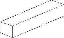 |
I took a square piece of cast iron and cut it into a long rectangle with ends of 10mm by 10mm. |
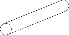 |
I put this rectangular section into a lathe and made it into a cylinder with a diameter of 9mm. |
From this I cut 10 equal length pieces each 15mm long. The top 5mm of each cylinder was cut using the lathe to have a diameter of 2mm as below. The measurements of the diameter were taken using a micrometer screw gauge.
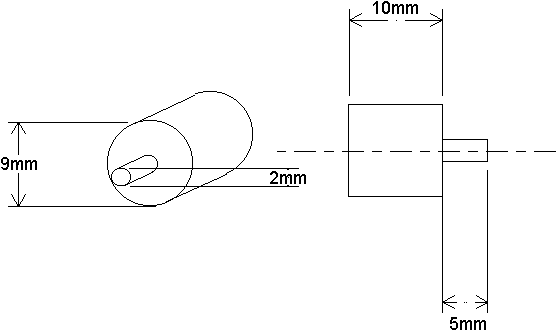
Above you can see the dimensions of each cast iron piece. To ensure accuracy all the blocks had to be identical or as near to identical as it is possible to get.
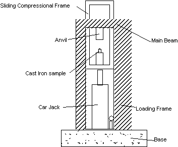
The larger 9mm diameter base is left to give the cylinder stability when it is in the compressor. Each of the samples is put in the compressive rig and an increasing load is applied to each piece until it breaks. The diagram below shows the compressive rig.
 |
As the car jack is pumped up it applies a pressure to the iron. The Picture on the left shows the compressor before the pressure is applied, the picture to the right is what is looks like afterwards. |
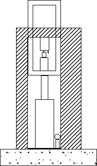 |
The pressure can be read off from the gauge which is connected to the car jack.
Adapting The Gauge |
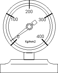
In order to measure the pressure at which the cast iron shears it was necessary to add a slave needle to the gauge which will tell us the pressure reached before the Iron snapped. In order for the needle to be put in I had to completely dismantle the gauge which is shown above and cut out a small cylinder of brass to lengthen the gauge shaft. A hole was drilled into the end of the brass cylinder so that it could be press fitted over the original shaft. The main needle was silver soldered onto the brass shaft.
 |
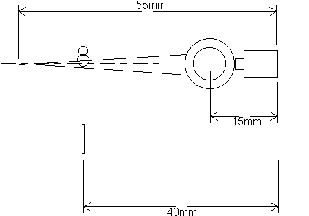
A slave needle was cut out of steel and was put onto the extended shaft so that it could move freely. A short length of brass wire was cut and silver soldered onto the slave needle 40mm from the end as shown to the left so that as the main needle moved it would push the slave needle with it. The needle was slightly curved downwards so that it would 'stick' at the point where it was pushed to by the main needle. |
Results |
I carried out the above experiment and I obtained the following results.
|
Test Number |
Pressure at which |
Pressure at which |
| 1 | 310 | 98.68 |
| 2 | 320 | 101.86 |
| 3 | 315 | 100.27 |
| 4 | 300 | 95.5 |
| 5 | 315 | 100.27 |
| 6 | 295 | 93.9 |
| 7 | 300 | 95.5 |
| 8 | 310 | 98.68 |
| 9 | 300 | 95.5 |
| 10 | 305 | 97.08 |
| Average | 97.72 |
These results are to the nearest 5kg due to the scale on the gauge. The pressure needed to break the sample per mm² is worked out by.
Pressure/mm² = Pressure at which iron sheared / (Π x r²)
These results were then plotted in a scatter graph showing the pressure at which each sample broke.
Conclusion |
These results are very close to what would be expected S.G Iron Properties And Applications said that the compressive strength of iron is 94-102kg/mm² and all but one of my results are in-between the boundaries. The average is 97.72kg/mm² which lies roughly between the two values. By looking at the samples 8 out of the 10 samples showed a shear of 45°. Two of the samples had just been broken up totally and showed no angle but this was probably due to a weakness in the metal or the sample being incorrectly placed in the compressor. The 45° angle can be seen in the photograph below. The angle on the picture appears to be slightly different to 45° but this is because the sample was not quite at 90° to the camera. The angle on the sample is 45°.
The reason that iron break at an angle of 45° is due to the structure of the atoms in the material. They are arranged in a way so that if enough pressure is applied the atoms will slide past each other at 45°.
Limitations |
- The tests were not all carried out on the same day so the temperature for the tests could have varied. A change in temperature can make the metal expand or contract and so lead to irregularities in the sizes of the samples.
- The lathe does not cut the metal smoothly, it leaves many small grooves and scratches in the metal which can cause it to be weak in places and so alter the load at which the sample would break. This could also account for the reason that two of the sample totally broke up when put under pressure instead of splitting at a 45° angle.
- The samples may have had sand or gas inclusions which may make them irregular and so reduce the accuracy of the tests.
- The scale on the gauge is only to the nearest 5kg so readings more accurate than to the nearest 5kg can not be taken.
Improvements / Extension Work |
- Instead of testing each sample individually a special rack could have been built to compress all the samples at once. However the pressure needed to compress 10 samples may have been to great to achieve. The shattered samples may also intermix unless they were somehow kept separate.
- The compressive rig could have been improved if a small pit was drilled into it the same diameter as the base of the iron samples as this would ensure that the samples are standing straight in the rack and do not fall over. This would ensure that the anvil comes straight down on the sample each time to ensure that all the tests are consistent.
- Different sizes of cast iron could have been used as by using samples with larger diameters it would be easier to see the 45° angle.
- Test could be done to see if the way that that the pressure applied to the iron affects it's compressive strength. In this experiment the pressure was applied gradually but if the pressure was applied very suddenly the results could be quite different. In order to do this a weight could be dropped from a fixed height which would apply a very sudden pressure to the samples.
Sources |
- SG Iron Properties & Applications
- Materials For The Engineering Technician - R.A. Higgins
